|
Step 1
From the main menu select the Print QSL - Design Pattern for print and PrintPreview
|
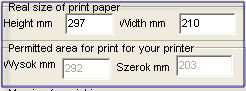
 | The appearance of the area no.1 type =
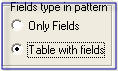
QSLScan pattern and type of
field in the pattern = Table with ields |
|
Step 2
We choose a Type pattern QSLScan and type fields in a pattern = Table with fields . After selecting this you will get the No.1 area in the form of the next. In the field Real dimensions of the QSL enter width (140 mm) and height(90 mm) measured to the nearest 1 mm QSL cards. Then select the field Background scan name file what holds the name of the scan performed Scan our QSL cards
Description of how to make a scan and at what resolution can be found here. .
|
 | | Window indicating the necessity of the Table in the pattern |
|
Step 3
Appear to us now a window indicating that necessary create Table in a pattern as a type field in the pattern we set the Table with fields .
|
 | Setting the parameters of the Table - No,of rows
and columns for Scan QSL |
|
Step 4 .
We must now determine the number of columns and rows that we use to design pattern (not a number of fields).At the begining, we note that the left and right sides of the column must be empty - which will better adapt to the required margins for your printer. So we need to add two 2-column to the required number of columns. The width of these columns, we can then reduce.
On the left side for example, you can not put a full field - because if we are align to the left side field we will start print near the left margin. Previously designated the left margin for a single printer may be too small when put in another printer. In this case, that could happen would be that our pattern will be well printed on a printer - but on the other is not. eg HP PSC printer has minimum margins left = 1.8 mm while the HP Laser Jet requires margin to 4 mm. Well then start printing a little further what will work correctly for different printers.
Therefore, I recommend adding a 2-th columns. For the same reason I recommend adding a 2-two blank rows - for the top and bottom. 1st row upper outside must meet another important role. Typically, the box CALL, or other 1st field is located approximately 1 / 3 hight of the card. "Broadening" So the width of 1st line so as to achieve a line beginning at the box CALL or 1st field.
So, the belt edge pattern must be added and leave it empty, ie do not merge the cells of the edge belt with any other cells
In determining the number of columns, we analyze our QSL card from the top and look how many field is needed for a given level of the line. Let us remember the 2 extra boxes, ie 1 field on the left side and 1 field to the right. Maximum number of columns on what comes out of this analysis is the number of columns that we need to set for the pattern. We performed a similar analysis for the vertical line which determines the number of rows
Set number of columns and rows for example to 9 and then click Insert table. . Pattern template with scan of QSL card will appear to us. In fact, there are two images - one for background and the second is a picture of the pattern truncated by the margins . Changing this margins will be affected to move the border between this two pictures. Take attention - program do rescaling image to the real dimension - what we are put in a real dimension QSL card fields - see putted value and dimensional line what you see
|

|
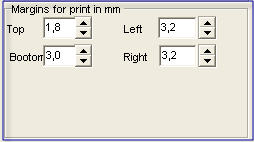
Step 5
Now change the side margins, ie. left, right, top and bottom
as show. The recommended margin values are 4 - 5.5 mm - but so as not to truncate the fields to print. Values of the width and height of the pattern are displayed in gray - and there is no access to them. With a change in the margin, these parameters are automatically changed.
|
 | Appearance of the pattern of Scan QSL
after the change margins but before
put any ADIF field |
|
Step 6
Next set appearance of the pattern after the change margins. Please note that due to the introduction of margin area the pattern is smaller, but still maintained a uniformity of distribution at 9 columns and 9 lines - now a little smaller. This uniformity is preserved until you change "Border cells" for different size boxes and placing 1st of the field ADIF
Entering the ADIF data fields can be made only if we see that our fields of pattern fit exactly to the fields of our scan. In this step, you can add or delete a row or column.
At this stage no longer try to put the ADIF field - as this may cause irregularities in the pattern and unexpected behavior of the program. Only in step 9 can add the ADIF field.
|

|
Step 6 A
In steps 6 A and 7 we show how to change the location of the borders cells to the entire card is always located in an area pattern and filled in 100% of its area. For this purpose program have function Alignment of cells in the right and down from the current cursor position. The function is carried out after placing the cursor in any cell pattern by click left mouse button and then clicking the right mouse button as shown next to the menu will expand.
This function can be also executed if fast pressed twice the left mouse button after placing the cursor in the cell from which to start the alignment. At this moment we are only interested in the above-mentioned functions. There we describe its action on the example
The function Alignment of cells to the right and down from the current cursor position , you can perform even if the pattern already contains the ADIF field. This allows you to edit the pattern .
If you gave pattern for such a station dx expedition with one of this country activity and you want pattern for another country activity provides the same fields ADIF - but located elsewhere in the cards because of some other theme to another. Then the pattern for the first card can be base for the second pattern and only you must change image from scan . Then, just move fields by using "borders" field to the new location and use function Alignment of cells in the right and down from the current cursor position
|
 | The appearance of the pattern when moves
guides to the down of the 1-st field -
if automatic alligment function is
switching to ON |
|
Step 6 B
In version 2.4 introduced the automatic alignment of cells from the cursor position. This feature if is selected checkbox, will bring up the automatic align function of cells in the right and down from the current cursor position. Moving the mouse wheel scroling no longer moving picture card, or this movement is very small, which disappears when you move the last fence. The current cursor position is calculated from the position of fence symbolizing the sliding line 
Calling the automatic alignment is carried out after releasing the left mouse button. In the cell under that mark appears when the cursor a little sign in the form of vertical bar |, symbolizing that from that cell alignment was made .
|
 | Abnormal appearance of the pattern in a version
2.2.0 --- by increasing the width and height fields
and scroling in the mouse downwards or right
button to the right |
|
Step 6 C
If the auto alignment is off, ie checkbox is checked off and the line shift has been made, then after scroling with use mouse wheel up and down you can get a picture similar to the image side. This happened because image occupied area that is larger than the area of QSL cards. . In the version 2.2.1 software equipped has functions discussed in Step 6 A - alignment on the right and down from the current cursor position, which can ben invoke manually or can be triggered automatically from Version 2.4 as in the previous step.
|
 | The appearance of the pattern when
you move all the lines |
|
Step 6 D
Appearance of the pattern when you move all the lines horizontally and vertically. You can disable automatic alignment, if we find that this function corrupts us some location of the line. At this point, the Undo feature works yet. As regards the compensation level is a line in it is made by the same component . HAM_SECRETARY not do horizontal alligment . It is posibility what do Windows component I can not disable this automatic horizontal align, but if any move the location anothers lines , you must do 2 time allign for this same vertical line - to obtain constans image what is not scrolled by mouse or from keyboard
|
 | Initiate alignment of cells down
from the current cursor position |
|
Step 6 E
Develop our pull-down menu if you press the right mouse button. With him, we choose the functions Alignment of cells in the right and down from the current cursor position . If you quickly press the left mouse button twice that menu does not appear, however, also this function will be do . We see that the height of the cells above the displaced boundary does not change. Scaling is done at the expense of developments in the hight cells lying below the sliding line. This change does not mean that all the cells below adopt the same height. Change the height is in proportion to the height of the previous row.
|
 | | Merge selected cells in a one cell on the QSL Scan pattern |
|
Step 7
Now, will cause some fields to reserve several adjacent fields merge the neighboring fields. This is done after selecting these fields with the mouse - click on the box holding the mouse and pull to the next cell. This do selecting these cells. Then, holding the mouse in the area of pattern press the right button which will expand pop-up menu and choose Merge selected cells
From the pop-up menu achieved by pressing the right mouse on the field can perform the following functions
| • | Inserts a row above the current cursor position |
| • | Inserts a row below the current cursor position |
| • | Deleting a row in which the cursor |
| • | Inserts columns to the left of the current cursor position |
| • | Inserts columns to the right of the current cursor position |
| • | Removing columns in the cursor is |
| • | Merge selected cells - only horizontal |
| • | Unmerge (disconnection) cells |
| • | Alignment of cells in the right and down from the current cursor position |
In this step, you can add or delete a row or column - with the exception of rows or columns of cells containing integrated cells.
|
 | CALL selected from the standard ADIF for
QSLScan pattern |
|
Step 8
First, set the font, size, align left, center, or right, and thickening of the BOLD we want to apply for a first field.Now inserts the field CALL by choose a field ADIF
Thus fixed font attributes will be valid until the next change the font attributes - no matter what font and size will be displayed for the next field
|
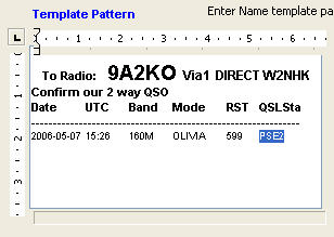
 | | Final form pattern template developed on the basis of the scan from QSL |
|
Step 9 and subsequent Step
These steps are similar to those described above, Steps 12 to 20 except that the operations carried out on cells of the table, which has yet to choose the vertical alignment buttons described above. Finally receive the appearance of the final pattern
|
 | QSLScan pattern for the rear blank page
before the border |
|
Step 21 design pattern with the border fields
Border Field can be used for any pattern - ie the type QSL full, labels for QSL, QSL Scan. We will discuss the issue on the basis of the type of pattern QSL Scan. The insert a border, we can make after the full design of the pattern, ie we have to perform steps 1 to Step 10 and subsequent point. Then we obtain the next pattern
|
 | | Selected area to the border |
|
Step 22
Now we introduce an area border for all the QSO's and the header fields. So select the area by placing the cursor in the first upper left cell of the area and "train" the mouse to the last field in the bottom right corner of the area as shown. This select the area in blue
|
 | Choosing the color of the border, and for all
line separating the cells |
|
Step 23
Now select the border color for the border line and all the lines separating the data from the drop-down menu
|
 | | Choosing the width of the border line |
|
Step 24
Then choose the size of the border line between 1 and 3-ch pixels. It should be emphasized here, and the size of the selected line will be mandatory for both the border line and the line of separation between the fields - which is associated with the element used on Windows that does not give here the possibility of different border width fields
|
 | The appearance of the pattern immediately
after the change line width |
|
Step 25
Appearance immediately after the change in the pattern line width. You can see that there is now a significant distortion of the pattern. This is because the width of the line that the previous separation was 1 pixel - now is 3 pixels - which here for 12 rows and 8 columns gives the rather large change. It should do so now - in this case as the next
| • | by hand move vertical line after the field QSL St. |
| • | you can try using the auto-alignment of fields on the right and down from the current cursor position - but better results you can obtain if you move manual vertical or horizontal lines borders of fields. |
|
 | Appearance when you move the border of fields --
best hand |
|
Step 26
The result is a moving boundary we obtain pattern as in the next
|
 | | Looks pattern after cover only the fields for QSO's |
|
Step 27
In a shown above pattern specially made a small mistake. The frame of the border covered fields SP9AUV Confirm our 2 way QSO at the top and TNX for QSO VY 73 de Jerzy. You can now fix it now by selecting the appropriate area and choosing the same line width = 3 pixels. A picture of the next.
|